
)


KICKER
713034020646
48KXMA9005
$719.99
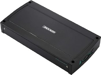
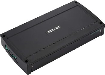
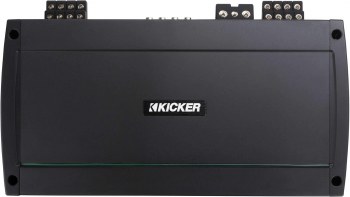
Marine Amplifier: The Kicker KXMA900.5 (48KXMA9005) 5-channel marine amplifier can provide 75 watts x 4 (4Ω), 125 watt x 4 output (2Ω), or two bridged outputs at 250 watts x 2 (4Ω), along with a mono subwoofer channel that can provide 400 watts (@ 2Ω or 1Ω) or 200 watts (@4Ω). Designed for the marine environment, the KXMA900.5 features marine-grade speaker terminals, stainless-steel screws, conformal-coated circuit boards, and ABYC/NMMA-compliant power and ground connections.
Note: The Kicker KXMA900.5 marine amplifier is not waterproof and should not be mounted where it will get wet.
Class D Amplification: The KXMA900.5 features state-of-the-art Class D amplification which provides ample power in a compact chassis. The 5-channel amp can provide the following power output:
- Main Channels (Amp1 & Amp2):
- 75 watts RMS x 4 @ 4 Ohms (@14.4V, ≤ 1% THD+N)
- 125 watts RMS x 4 @ 2 Ohms (@14.4V, ≤ 1% THD+N)
- 250 watts RMS x 2 @ 4 Ohms bridged (@14.4V, ≤ 1% THD+N)
- Subwoofer Channel:
- 200 watts RMS x 1 @ 4 Ohms (@14.4V, ≤1.5% THD+N)
- 400 watts RMS x 1 @ 2 Ohms (@14.4V, ≤1.5% THD+N)
- 400 watts RMS x 1 @ 1 Ohm (@14.4V, ≤1.5% THD+N)
Common Controls & Indicators: Amplifier RCA input and speaker output channels are configured as Amp 1, Amp 2, and Sub, each with 2 RCA channels. Common controls and indicators for Amp 1 and Amp 2 include:
- Input Level: 2-position switch; select High (speaker-level) or Low (line-level).
- Fader: On/Off push-button is used to select whether the four input channels will be fed from 1 pair of RCA inputs or 2 pairs (front/rear).
- Sub Input: 2-position switch lets you select the input signal for the subwoofer channel - Sub or Amp 2.
- Auto Turn-on: The amplifier has three methods of turning on via a 3-way switch: +12V, DC Offset, and Audio:
- +12V: The preferred method (+12V) is to run an 18-gauge wire from the remote turn-on lead of the source unit to the Remote (REM) terminal on the amp. When a +12V signal is detected on the wire, the amplifier will turn on.
- DC Offset: If your source unit lacks a remote turn-on lead (a factory head unit, for example), you can choose to turn on the amplifier via the DC Offset method. When a DC offset is detected (>3 volts) on the speaker-level inputs, the amplifier automatically turns on.
- Audio (Signal Sense): This method detects an incoming audio signal from your source unit (speaker-level) and automatically turns on the amp.
Note: If using either the DC Offset or Audio methods of powering the amplifier On/Off, the REM terminal becomes a +12V output that can be used for activating additional amplifiers.
- PRT LED: A red Protect LED can let you know if a problem arises.
- Flickering: A flickering PRT LED can indicate low-voltage from the battery, either from a low battery or a weak power/ground connection.
- On Solid: This can indicate Thermal Shutdown, if the amp gets too hot; Shorted speaker output; or Low Voltage, if the incoming power is not within the 10V-16V operating range.
Amp 1 Controls:
- Input Gain Control: continuously variable from 125mV to 5V with the Input Level switch set to Low; 250mV to 10V with the Input Level switch set to High. The Gain control features a backlit "Optimal Input" LED indicator that will light if the Gain is set too high and the incoming signal starts to clip. The Gain control should be backed down just below the clipping (indicator On) point.
- Crossover Switch: 3-position switch; select Off, High Pass, or Low Pass; the slope is 24dB/octave.
- Frequency Range: 2-way switch sets the Frequency range for the filter to x1 or x10.
- Frequency: a rotary control; continuously variable from 10Hz-500Hz (x1), or 100Hz-5kHz (x10)
Amp 2 Controls:
- Input Gain Control: continuously variable from 125mV to 5V with the Input Level switch set to Low; 250mV to 10V with the Input Level switch set to High. The Gain control features a backlit "Optimal Input" LED indicator that will light if the Gain is set too high and the incoming signal starts to clip. The Gain control should be backed down just below the clipping (indicator On) point.
- Crossover Switch: 4-position switch; select Off, High Pass, Low Pass, or Bandpass; the slope is 24dB/octave.
- HP Frequency: a rotary control; continuously variable from 10Hz-500Hz.
- Low-Pass Range: 2-way switch sets the Frequency range for the Low-Pass filter to x1 or x10.
- LP Frequency: a rotary control; range depends on Low-Pass Range switch; continuously variable from 40Hz-500Hz (x1), 400Hz-5000Hz (x10).
Sub Controls:
- Input Gain Control: continuously variable from 125mV to 5V with the Input Level switch set to Low; 250mV to 10V with the Input Level switch set to High. The Gain control features a backlit "Optimal Input" LED indicator that will light if the Gain is set too high and the incoming signal starts to clip. The Gain control should be backed down just below the clipping (indicator On) point.
- LP Frequency: a rotary control; continuously variable from 40Hz-160Hz.
- Sub-Sonic: a rotary control provides sub-sonic filtering; continuously variable from 10Hz-80Hz.
- KickEQ+ Bass Boost: a rotary control lets you increase the bass level between 0dB and +6dB; centered at 40Hz.
Wire Connections: The KXMA900.5 has screw-down terminals for the power, ground, turn-on (REM), and speaker outputs. The Power and Ground slots are 0.30" wide and the Remote and Speaker slots are 0.21" wide. 4 AWG power and ground wires are recommended (sold separately). The Power and Ground terminals are ABYC/NMMA compliant for marine installations.
External Fuse: The amplifier does not include a built-in fuse, therefore an external fuse should be placed on the power wire, within 18" of the battery. It is recommended that a 4-gauge amplifier wiring kit and a 100-amp external fuse be used when installing the amplifier.
Note: Currently Kicker will extend the standard warranty by an additional year (for a total of three years) when a qualifying Kicker Installation Kit is purchased with the amplifier.
Input Signal: The KXMA900.5 accepts either High (speaker-level) or Low (line-level) input signals on the three pairs of RCA inputs, selectable using the input level switch on the end of the amp. When using a speaker-level input signal, add the optional Kicker KiSL speaker-level to RCA adapter (sold separately). The input sensitivity is 125mV-5V (low) or 250mV-10V (high).
Remote Bass Level Control: The KXMA900.5 amplifier includes a KMBLC Remote Bass Level control for adjusting the output level from the front seat. The Remote Bass Level Control can be mounted under a dash or console and includes a 19.5' remote cable (RJ-11 connectors on both ends).
Dimensions: When mounted horizontally, the KXMA900.5 dimensions are:
- Width: 12.75"
- Height: 2.19"
- Depth: 8.26" (not including wire)
- 5-channel marine amplifier
- 75 watts RMS x 4 + 200 watts RMS x 1 at 4 ohms
- 125 watts RMS x 4 at 2 ohms + 400 watts RMS x 1 at 1 or 2 ohms
- 250 watts RMS x 2 bridged at 4 ohms + 400 watts RMS x 1 at 2 ohms
- subwoofer channel 1-ohm stable — 400 watts RMS (+/-10%) x 1 at 1 ohm)
- Class D amp technology
- gain knobs also function as clip lights
- Amp 1: variable high- or low-pass filter (10-500 Hz, 24 dB/octave), plus 10x switch
- Amp 2: variable high-pass (10-500 Hz, 24 dB/octave), low-pass (40-500 Hz, 24 dB/octave with 10x switch), or bandpass (engages both) filter
- Sub channel: variable low-pass filter (40-160 Hz, 24 dB/octave), subsonic filter (10-80 Hz, 24 dB/octave), and variable bass boost (0-6 dB at 40 Hz)
- wired remote bass knob control
- weather-resistant conformal-coated circuit boards
- front-mounted controls protected behind gasket-sealed fold-down door
- Fail-Safe Integration Technology eliminates noise from your vehicle's electrical system
- preamp and speaker-level inputs (speaker wire to RCA adapter required for speaker-level input)
- wiring and hardware not included with amplifier
- 4-gauge power and ground leads and a 100-amp fuse recommended
- for multiple amplifiers, an additional 100-amp in-line fuse between the distribution block and this amplifier is recommended
- dimensions: 12.75"W x 2.19"H x 8.26"D
Support
![]()
Manuals
2021 KXMA 5-Channel Amplifier | Multilingual - Download
2021 KXMA 5-Channel Amplifier Info Card | Multilingual - Download
![]()
Support Links
Amplifier Power Testing
Subwoofer / Speaker FAQ
Box Building Help
Wiring Diagrams


")


Recently Viewed Items


